Beyonwiz AD055H018 MODEL PSU Repair - UPDATE 25-09-2012

Beyonwiz HD PVR / Network Media Players including Freeview models.

Moderators: Gully, peteru

User avatar
warkus
Guru
Posts: 712
Joined: Tue Dec 09, 2008 15:14
Location: Perth, WA

Beyonwiz AD055H018 MODEL PSU Repair - UPDATE 25-09-2012

Post by warkus » Wed Feb 25, 2009 19:55

------------------------------------------------------------------------------------------------------------------------------------------------------------

THIS IS A GUIDE ON REPAIRING YOUR BEYONWIZ A&D AD055H018 POWER SUPPLY UNIT (OLD STYLE)

WARNING – IF YOU HAVE ANY OTHER MODEL – DO NOT FOLLOW THIS GUIDE - EMAIL ME FOR FURTHER ASSISTANCE (SEE REVISION HISTORY FOR CONTACT DETAILS)

Last updated 25/09/2012 (Changes and updates listed in the revision history)

THANKS to ALL OF THE MODERATORS AND FORUM REGULARS who have helped to keep this thread and more importantly this forum going!!! You know who you are!

------------------------------------------------------------------------------------------------------------------------------------------------------------

** BRAND WARNING - DO NOT USE SUNTAN BRAND CAPACITORS TO COMPLETE THIS REPAIR **

...Or any other cheap brand for that matter. Please ensure that you follow this guide carefully, it tells you which brands to use and even lists part numbers further down.

Your local electronics enthusiast shops are not always a good place to source "good quality" electronic components. Try a more professional outlet such as Element 14 (Farnell) or RS Components or even XON Electronics. All can be ordered online and delivered to your door - it is worth the few extra days in delivery!

------------------------------------------------------------------------------------------------------------------------------------------------------------

** REPAIR THREAD - AMMENDMENT NOTE **

The works contained in this guide are based purely on my own knowledge of repairing this model of power supply combined with 20 years’ experience in the industry. As the age of these units increases, and therefore the amount of running time each machine has received increases, new components may be discovered as faulty. When this occurs I will update the guide as I have here today to detail any new possible issues and resolutions that Beyonwiz owners may need to know about.

If you have already completed this repair on your machine, it would be a good idea to review this latest update and potentially complete the amended modifications. This update to the repair guide is a MAJOR OVERHAUL and will require AT LEAST 2 HOURS of your time to complete it properly. The repair is not just about replacing capacitors, there is more to it than that and I urge you to read it carefully and follow ALL recommendations along the way to ensure that your PSU is working correctly at the end of the repair.

------------------------------------------------------------------------------------------------------------------------------------------------------------

Why would you want to attempt to do this repair? (Besides the fact that you love your Beyonwiz)…

Here is a list of reasons that *may* be getting you frustrated with your machine.

* HDD checks being performed regularly for no reason, i.e., each time you power the unit on
* Unstable operation, boot failure & system lockup
* Lost recordings & corrupt HDD (This can also be caused by the HDD cable which gets brittle from heat)
* HDD isn’t detected by the BW but the HDD has tested ok in a PC or other PVR
* Colour distortion & abnormal looking output through HDMI or no HDMI output at all
* WIFI no longer working properly when it previously was working
* DIM DISPLAY on the front panel of your unit - Faint and not as bright as it was or not there at all
* DVD player problems such as failure to playback disks that DO normally work ok
* DVD drive opening and closing for no reason randomly
* ERROR 0000 on system start-up
* Wired network failure & USB failure (very bad sign – stop using machine ASAP if this occurs)

NOTE – This is a broad list of the common failures for the Beyonwiz DP-S1 machines that use this model PSU. Failures however are NOT limited to this list only and other issues may also be experienced. If this sounds familiar then it might be time for you to give your beloved Beyonwiz a makeover.

THIS MODEL PSU IS FOUND IN ORIGINAL MODEL DP-S1 UNITS ONLY. I HAVE NAMED THE REPAIR THREAD BY THE PSU MODEL NUMBER.

------------------------------------------------------------------------------------------------------------------------------------------------------------

TABLE OF CONTENTS

SECTION 1 - DISCLAIMER & GENERAL WARNING - READ BEFORE YOU BEGIN
SECTION 2 - GENERAL ASSUMPTIONS, INFORMATION AND TOOLS REQUIRED FOR THE JOB
SECTION 3 - AN OVERVIEW OF THE WORK REQUIRED
SECTION 4 - MAKING A DISCHARGE TOOL IF YOU DON’T HAVE ONE
SECTION 5 - REMOVAL OF THE PSU UNIT FROM YOUR BEYONWIZ
SECTION 6 - REPAIRING YOUR PSU UNIT
SECTION 7 - RE-ASSEMBLING YOUR BEYONWIZ
SECTION 8 - TESTING AND FINAL NOTES
SECTION 9 - REVISION HISTORY


------------------------------------------------------------------------------------------------------------------------------------------------------------

SECTION 1 - DISCLAIMER & GENERAL WARNING - READ BEFORE YOU BEGIN

I TAKE NO RESPONSIBILITY FOR WHAT YOU MAY DO TO YOUR OWN PSU OR PVR. THIS REPAIR IS PROVIDED FOR GUIDANCE ONLY AND IS INTENDED FOR EXPERIENCED USERS WITH ELECTRONICS KNOWLEDGE.

DO NOT ATTEMPT TO REPAIR A 240v PSU UNLESS YOU KNOW WHAT YOU ARE DOING!

IF YOU ARE ATTEMPTING SOMETHING LIKE THIS FOR THE FIRST TIME – THINK TWICE AND THEN THINK AGAIN!

THIS PSU WILL STILL CONTAIN VERY HIGH VOLTAGE EVEN WHEN DISCONNECTED.

THE HIGH VOLTAGE SIDE OF THE PSU RUNS AT AROUND 350v – MUCH HIGHER THAN 240v ONCE CONVERTED TO DC VOLTAGE – STAY AWARE AT ALL TIMES.


------------------------------------------------------------------------------------------------------------------------------------------------------------

SECTION 2 - GENERAL ASSUMPTIONS, INFORMATION AND TOOLS REQUIRED FOR THE JOB

To begin, I have made some basic assumptions, if you are contemplating this repair, then…

Firstly, I imaging you must own the basic equipment or can at least get it…
Secondly, you know something about electronics and are aware of what a capacitor is…
Lastly, you are familiar with removing and installing electronic components…

If you fail on any of these points you should turn back now. Feel free to contact me and I can arrange to assist you with the repairs. (See revision history below for ways to contact me).

Equipment you will need for the repair...

A 25w Soldering Iron or Temperature Controlled Iron (Set to a temperature of no more than 400°)
Good Quality Solder & De-Soldering Braid or Solder Removal Tool
Discharge Tool (Instructions a little further down)
Wire Cutters & A Philips Screw Driver

Do not use a soldering iron that is TOO HOT as you can severely damage the PCB and/or other components. Equally, do not use anything less than 25w (i.e. 15w) as the negative tracks that you will be soldering are wide, and cover a considerable part of the PCB in the area you are working on. They will take a bit of heat to melt and replace the solder in a clean and appropriate way. Considerable frustration will occur if you use a soldering iron that is TOO LOW in temperature.

------------------------------------------------------------------------------------------------------------------------------------------------------------

SECTION 3 - AN OVERVIEW OF THE WORK REQUIRED

PICTURE 1 below displays the FIFTEEN (15) capacitors that should be replaced for continued longevity of your PSU. There are lots of arrows and colours, so follow them CAREFULLY and refer to PICTURE 4 as well showing the PCB joints on the back of the board further down. The colours match PICTURE 1.


Image

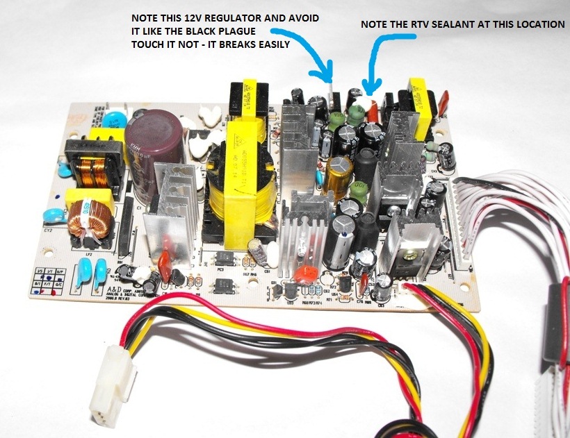
(PICTURE 1 - YOUR PSU, AN OVERVIEW - WHAT TO REPLACE...)


These capacitors relate to and filter the many power rails of the power supply. Sometimes these capacitors are raised up and are swollen/split at the top or bottom, but this is NOT ALWAYS the case, and if yours are not swollen, it definitely DOES NOT mean that your capacitors are therefore ok. Replace them all regardless.

You may see a white/cream coloured glue/resin covering some of the components. This is an RTV electrical rubber sealant that the manufacturer uses to “hold” components in place and stop micro vibration that can occur, so don’t mistake this with leaking or broken parts. Depending on the revision/batch of your PSU board, sometimes it covers the capacitors you are replacing, and other revisions/batches it does not. Either way, ignore it and if need be use a knife to cut the capacitors free if you need to. It will almost certainly be on the 220uf 16v capacitor closest to the back of the wiz case (see yellow arrows above). BE CAREFUL when cutting and removing the silicone at this location. I will go into why further down.

Additional to the replacement of these capacitors, you will need to re-solder many of your PCB solder joints as they will by now have started to crack and become “dry” so to speak. You will need to inspect the PCB and look for poor solder joints with obvious cracking on them. There is ALWAYS at least 20 – 30 of them when I do a repair. If you can’t find any then you are not looking hard enough. I will go into more on this later on.

------------------------------------------------------------------------------------------------------------------------------------------------------------

SECTION 4 - MAKING A DISCHARGE TOOL IF YOU DON'T HAVE ONE

Even when the unit is disconnected from mains power, the risk of shock or shorting from the PSU unit is high. The mains capacitor can hold considerable voltage. You should as a matter of precaution discharge the mains circuit BEFORE you repair the PSU. Do this using a suitable discharging tool or make your own as detailed here.

Making a Capacitor Discharge Tool - You can make a capacitor discharge tool fairly easily. You will need…

2 x INSULATED alligator clips
40cm of 14awg stranded wire
10k ohm, wire-wound, 10 WATT RESISTOR

Solder an alligator clip to both ends of the 40cm wire. Then cut the wire about 18cm along from one end, and solder the resistor in place onto both cut ends. Now wrap the resistor and solder points with at least THREE layers of ELECTRICAL TAPE. Alternatively, you can use heat shrink tube, at least 2 layers of it, one over the other. PICTURE 2 below is what it should look like when finished, or similar anyway!


Image

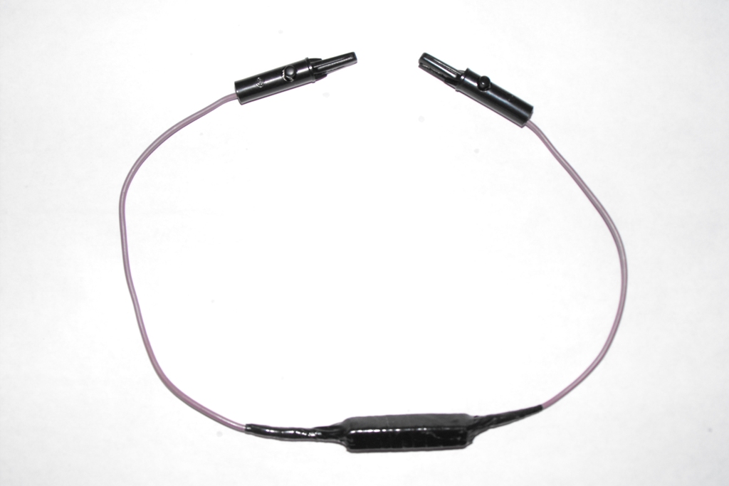
(PICTURE 2 - THE FINISHED DISCHARGING TOOL, WHAT IT SHOULD ROUGHLY LOOK LIKE, NOT VERY EXCITING REALLY IS IT''')


(DO NOT TRY TO DISCHARGE YET - SEE BELOW IN THE "REPAIRING YOUR PSU UNIT" SECTION FOR WHEN TO DO THIS)

------------------------------------------------------------------------------------------------------------------------------------------------------------

SECTION 5 - REMOVAL OF THE PSU UNIT FROM YOUR BEYONWIZ

1. REMOVE POWER FROM THE BEYONWIZ MACHINE, ensure that the power cable is unplugged, not just turned off. This sounds like the most obvious point doesn’t it, but surprisingly it isn’t!!!

2. Next you need to remove your side grey "wings" if they are not already removed (many take them off for visual reasons). To do this, turn your unit over GENTLY and you should see a clip holding the grey side "wings" of your unit into place. Push the clip down into the unit, and slide the wing towards the front of the case, it will then come off. Take BOTH off, and then turn your unit back up the right way.

3. Unscrew and remove the TWO (2) side case screws and FOUR (4) rear case screws from your unit and remove the lid by sliding it back and then lift it upwards.

4. Disconnect the mains voltage power connector from the PSU. To remove this you will need to push the connector lock in as you pull it up and off the board. (Top left cable in PICTURE 1). Refer to POINT 1 above before doing this!

5. Place something to use as a temporary basic insulator (a small book is good) on top of the DVD drive.

6. Disconnect the BW mainboard power cable FROM THE MAINBOARD – this cable is NOT removable from the PSU. To remove it off the mainboard, push the connector lock in as you pull it up and off.

7. Unscrew and remove the FIVE (5) screws holding the PSU in place and lift the PSU up and out of the BW case by its edges being sure to avoid touching any components, it will still contain stored voltage at this time. As it will still be connected your Hard Drive and DVD Drive at this stage, you will need to place it on top of the "small book" or insulator you previously put onto the DVD drive. Now you will have a lot more room to get your hand in under the DVD drive and remove the power cable from it. No cut hands today!

8. Now you can disconnect the DVD power cable and the HDD power cable (not the IDE cable) from the back of the drives, this cable is NOT removable from the PSU. Lift the PSU up carefully by the edges and get ready to repair it! You should now be staring at your power supply. It “should” look something like PICTURE 3 below.


Image

(PICTURE 3 - YOUR PSU REMOVED, THE LIFE-SOURCE OF YOUR WIZ...)

------------------------------------------------------------------------------------------------------------------------------------------------------------

SECTION 6 - REPAIRING YOUR PSU UNIT

If you carefully turn your PSU over and look at the solder side of the PCB, you can familiarise yourself with where the points are that you will need to unsolder. Refer to PICTURE 4 below.

At this point you should DISCHARGE any stored voltage from the mains capacitor. As mentioned already, the stored voltage here can cause you big problems, least of all would be shorting/sparking the unit, and worst would be hurting yourself considerably. See SECTION 3 above for more information on making a discharging tool if you do not have one.

Discharging the mains capacitor – The capacitor that will need discharging is the BIG 400v mains capacitor on the HIGH VOLTAGE side of the PCB. If you have followed the instructions this far, then your unit will be off, disassembled and you should be staring at the solder side of your power supply PCB. If not, go back up and follow the previous instructions.

Carefully connect the alligator clips to the capacitor terminals/solder points on the PCB (one clip to each exposed terminal, don’t short them!). Look at PICTURE 4 below for the location of the BIG 400v capacitor solder points, I have marked them in GREY. Once attached, the resistor will drop the voltage down in around a minute or so, count to 90 slowly and then unclip and you’re done. Test using a multimeter if you have one to ensure that the voltage is nil.

Now it's time to replace the capacitors on the board. You will need to replace 15 capacitors in total. The voltage and specification for each capacitor is detailed in PICTURE 1 above. I have also detailed the PCB PART NUMBERS below as well as providing PANASONIC PART NUMBERS for ordering replacements from Element 14 (Farnell) or RS Components (below).

In PICTURE 4, you can see the underside of the PSU board, and as mentioned above I have colour marked the points you will need to unsolder in the same colours as PICTURE 1 above.


Image

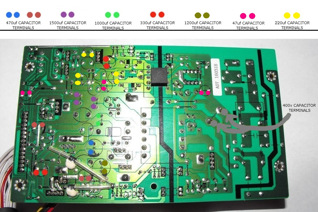
(PICTURE 4 - THE UNDERSIDE OF YOUR PSU, WHAT TO UNSOLDER...)


Below are the PCB PART NUMBERS to replace and also a SUGGESTED REPLACEMENT for each.
(All replacements listed below have been specifically selected for their quality, SIZE and suitability)

C53 & C60 - 470uf 16v
REPLACEMENT PANASONIC FR SERIES P/N: EEUFR1V471L - 470uf 35v

C54 - 470uf 25v
REPLACEMENT PANASONIC FR SERIES P/N: EEUFR1V471L - 470uf 35v

C55 & C35 - 330uf 25v
REPLACEMENT PANASONIC FR SERIES P/N: EEUFR1H331L - 330uf 50v

C58 & C59 - 1500uf 10v
REPLACEMENT PANASONIC FR SERIES P/N: EEUFR1C152L - 1500uf 16v

C56 - 1000uf 25v
REPLACEMENT PANASONIC FR SERIES P/N: EEUFR1E102L - 1000uf 25v

C52 - 1200uf 16v
REPLACEMENT PANASONIC FR SERIES P/N: EEUFR1E122L - 1200uf 25v

C7 & C41 & C43 - 47uf 50v
REPLACEMENT PANASONIC FR SERIES P/N: EEUFR1J470 - 47uf 63v

C37 & C44 & C46 - 220uf 16v
REPLACEMENT PANASONIC FR SERIES P/N: EEUFR1C221 - 220uf 16v

Unsolder and remove the old capacitors one at a time and then use solder braid to clean off any solder left on the PCB solder pad. This will then leave you a nice clean, unblocked hole (2 of them for each capacitor) for which you can then drop in your new capacitor and line it up before soldering it in permanently. Once you have soldered each capacitor into place, remove the excess wire/leg of the capacitor using wire cutters, it should be cut flush with the solder pad, as per all other joints on the PCB. When unsoldering and soldering one of the 470uf capacitors (shown on PICTURE 4 above as the dark red/burgundy colour) please pay particular attention to soldering this area and DO NOT melt the plastic shield covering the TVS diode that runs right next to the capacitor points you need to work on. To assist with this, take a look at PICTURE 5 below for a way to make your life easier when soldering in this capacitor!

Another point you should note while working on your power supply – PAY CAREFUL ATTENTION TO THE REGULATOR SHOWN IN PICTURE 3 ABOVE. This regulator is notoriously bad. It has no heat sink and usually no RTV sealant on it and the slightest movement of it will almost certainly crack the PCB joints underneath. Over time it has gotten very brittle around that area on the PCB. You will need to replace a 220uf 16v capacitor (C46) right next to that regulator and 2 others close by. C46 almost always has sealant on it.

Be careful removing and replacing C46 and you should be right. Check and resolder the 3 legs of the regulator once you have finished replacing that capacitor and the others around it just to be sure that is hasn’t cracked off the board. This is a common problem and if yours is loose or has cracked and lifted up the PCB tracks, then you will need to do remedial repair work on it to fix it, which includes scraping back the green protective coating on the tracks leading away from the regulator and re-solder everything with a thick trail of solder to secure it better and bridge the breaks in the PCB tracks. Not an easy job.

Now assuming everything went well in replacing the 15 capacitors, now what? Clean the flux off your board with Turps or flux/PCB cleaner so that you can see the board clearly. Then get a nice white bright lamp or torch and inspect your PCB. There will almost certainly be a LOT of dry joints on your PSU, especially around the area of the regulator mentioned above, and in the high voltage area too. They should be easy to identify. Spend the time and MAKE SURE you go over them properly, ensuring you don’t short any of the joints out with other joints on the board. It can sometimes be really hard to resolder the joints properly as there is a protective lacquer coating over the board which makes it pretty hard for the solder to stick. Scraping the affected legs with a blade BEFORE soldering them helps to make the solder stick better if need be.


Image

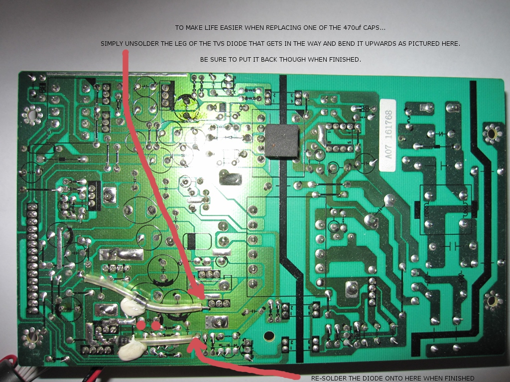
(PICTURE 5 - MAKING IT EASIER TO REPLACE ONE OF THE 470UF CAPACITORS LOCATED NEAR THE TRANSIENT VOLTAGE SUPPRESSOR...)


So let’s double check where we are at now and make sure the workmanship is up to scratch… Ensure that you have installed the 15 capacitors around the correct way, they are all polarised and must be installed correctly. The – (or negative) of the capacitor is marked on the side of the capacitor as well as on the component side of the PCB. Double check your handy work as a safe guard before going any further. Are they all ok? So the caps are installed correctly, and all the obvious dry joints have been resoldered nicely with NO SHORTING (double check that too). Basically you’re itching to get it back into the machine right??? Well not quite yet…

The last thing you need to do in the repair before signing off on it is prevent shorting of one of the diodes underneath the PCB (if not already too late), shown in PICTURE 6 below. Basically the heat protective cover around the 2 diodes degrade over time with heat, and sometimes the diode can short on other component legs that it happens to be lying over the top of. This is bad - very bad. If it has happened you will almost certainly have issues with your mainboard even after repairing the PSU.

PICTURE 6 is a close up of the diodes and of the 2 joints usually responsible for the diode shorting out. If you look closely, the edge of one of the joints is underneath the diode and the other is just about touching the right side of the diode. Because the 2 legs bend and point inwards towards the diode, it reduces the space between the legs and the diode cannot sit flat on the PCB, and instead usually lies across the joints. Over time heat wins and the leg of the component below penetrates the heat shield of the diode and hey presto, it shorts.

To avoid this unsolder the leg of the diode pointed to by the RED arrow and bend it up. Then using a flat bladed screw driver, bend the 2 legs pointed to by the PURLE arrows so that they point outwards away from the diode instead of inwards onto the diode. Once bent correctly, resolder the 2 joints to make sure they are ok and then bend the diode back down and resolder it into place as well. This will allow the diode to sit happily between these 2 joints without any chance of it shorting in the future.


Image

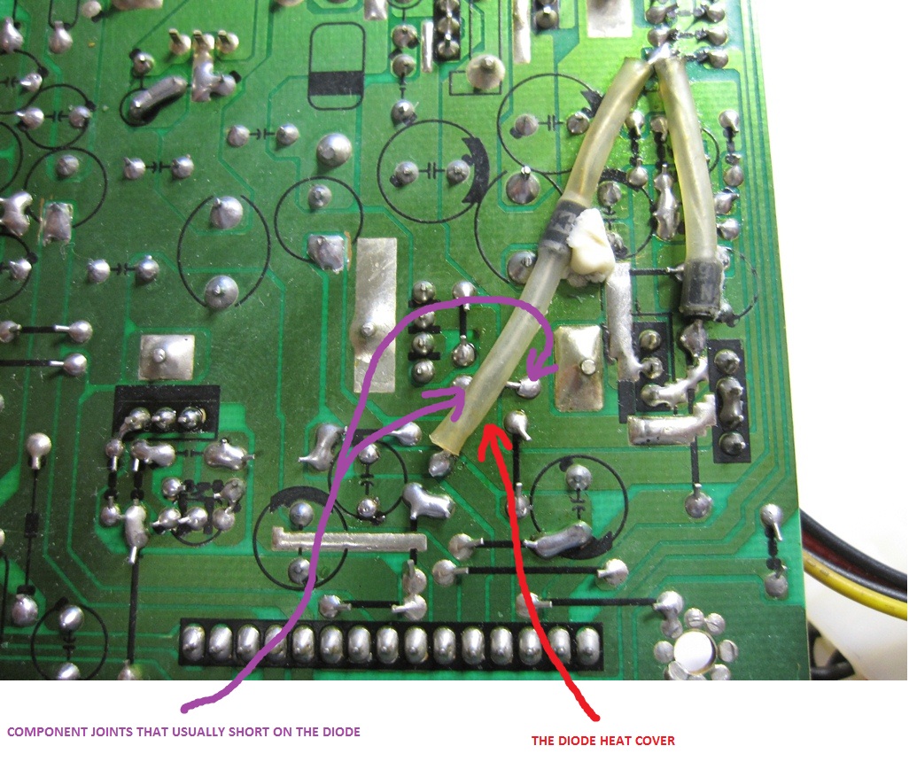
(PICTURE 6 - A CLOSE-UP OF THE DIODE ON THE UNDERSIDE OF THE PSU - MAKE SURE IT IS NOT SHORTING OUT...)


OK,

Final check – Again, make sure your soldering is up to scratch, no shorts, and the components are lined up correctly. Have you replaced the ENDS OF THE DIODE shown above in both PICTURE 5 and PICTURE 6? All ready to go?

Ok, time to reinstall. I’ll bet you’re over it by now but the end is near so don’t quit just yet.

------------------------------------------------------------------------------------------------------------------------------------------------------------

SECTION 7 - REASSEMBLING YOUR BEYONWIZ

To RE-ASSEMBLE your PSU unit into your Beyonwiz…

1. Place the PSU back onto the insulator you put on your DVD drive (the small book). Try to put it on there the same as you had it when you removed it, i.e. line it up the same, upside down if that's how you took it out etc. This will help with the re-connection of the cables attached to it.

2 Connect the Hard drive and & DVD drive power cables BEFORE you place the PSU back onto its original mounting holes. This will assist you in getting your hands under the DVD drive in order to reconnect the power cable.

3. Now place the PSU back into its proper home, make sure the cables are not caught underneath, line it up so that the FIVE (5) screw holes are aligned to the case mounts, then replace the screws you took out and secure the PSU.

4. Reconnect the BW mainboard power cable to the mainboard. Line it up and push down, it should click into place and will not fit on properly the wrong way around.

5. Check to make sure the IDE cable is still pushed in tight in both the hard drive & DVD drive, sometimes it can work loose.

6. Reconnect the mains power cable to the PSU. Line it up and push down, it should click into place.

That’s it. You’re basically ready to go. Do not replace the lid just yet, do some testing first.

------------------------------------------------------------------------------------------------------------------------------------------------------------

SECTION 8 - TESTING AND FINAL NOTES

Before replacing the lid and installing your unit back into its permanent home, test it for power and function. A basic test would be to turn it on and check for standby power. At this point power the wiz up and check that the unit goes from standby to “on”, and then check that the HDD powers up, the DVD works, and that you have output to a TV/monitor. If that’s all good, then you can do further functionality tests whenever you are ready. Depending on how bad your PSU was, you may well need to format your Hard Drive, this is quite normal, and at the very least you may need to do a HDD Check, this does not mean your PSU is still faulty.

There is also every possibility you will need to REPLACE the IDE cable as well and there is no time like now to do it being that the wiz is open. They tend to get very brittle. It needs a longer than standard cable, at least 55cm in total length with a fairly long space between the HDD and DVD connectors. Not the easiest cables to find but they do exist. DO NOT exceed a cable length of 65cm-70cm AT ABSOLUTE MOST as you will have issues with data corruption and HDD problems if you do. 80cm and 100cm cables are no good to use.

While the unit is open and using a multi meter, you may also wish to test the following voltage regulators on the mainboard as they are PRONE to failure if your PSU was really bad before repair. Once your PSU is properly restored and installed back into your wiz, power it up and carefully test U703 & U404. The first is pretty much in the middle of the board and is a 3.3v regulator, the top tip of the regulator is positive. The second regulator is almost under the wireless module and is a 2.5v regulator. This one goes high quite often and causes complete failure of your USB ports & network port.

If U404 has gone high, then there is little chance of ever getting the wired network or USB ports to work again sadly without replacing your USB controller IC and network controller IC. Replacement of these regulators is not easy and not recommended for anyone without experience. I recommend contacting me for further assistance with this where required. I try to be available as much as possible for anyone that may need assistance with the repair but sometimes there may be delays in reply.

Ok, Now that you have… completed your testing, are happy with the result, the unit now has a bright front display again, and all features are working well - you can relax, put the lid back on and replace the 6 case screws and 2 grey wings. Job done! The cost apparently of replacing this PSU with a new one from Beyonwiz is upwards of $150+ excluding delivery or labour to fit it. This repair should cost you no more than $25 in capacitors plus maybe a bit for delivery if you order them online and of course the cost of your time too!

To anyone that would like me to do it for them, I can do… for a very low and reasonable amount, which varies on how bad your PSU is, as it takes a LONG TIME to repair these units properly. (See revision history below for ways to contact me). I do not repair these for the money / profit as anyone who has used me would know.

I hope this assists many users with extending the life of their units!

------------------------------------------------------------------------------------------------------------------------------------------------------------

SECTION 9 - REVISION HISTORY

Version Changes & Updates…

1.0 - (25/02/2009)
Initial write up - 1 picture included

1.1 - (26/02/2009)
Added/changed discharge tool information
Added various other minor little bits n pieces to enhance what was there

1.2 - (26/02/2009)
Structured the guide better
Added table of contents
Fixed some spelling/grammar

1.3 - (27/02/2009)
Added detail to the picture

1.4 - (10/04/2009)
Added advice to replace an extra capacitor
Added detail to PICTURE 1
Minor enhancements and additional information throughout
Added an extra 4 pictures (5 pictures in total now)

1.5 - (08/05/2010)
Added additional symptoms to the list above (As the units are getting older, there are now a few more obvious symptoms that are caused by the PSU failing)

2.0 - (02/11/2010)
Added 2 new capacitors into the repair that cause the DIM DISPLAY ISSUE.
Modified the pictures to reflect this
Added a new picture
Made general modifications to the info in the guide to "enhance" it somewhat
Included a more detailed removal and re-installation guide for the PSU
Detailed the reason behind the addition of the new capacitors
Fixed some spelling errors
Changed the 470uf capacitor replacements from 25v to 35v as they are no bigger in physical width, just taller.

2.1 - (15/07/2011)
Made into a downloadable PDF version - Download it from the link below.

3.0 - (25/09/2012)
Major Overhaul
Added a heap more capacitors to replace
Documented soldering of Dry Joints
Detailed other problems encountered
Various fix-ups and removal of waffle
Updated downloadable version to the same as online
Removed a picture
Added a picture
Documented Diode shorting issues
Documented Checking Mainboard Regulators

For repair assistance with this or other BEYONWIZ models - please visit my web site - http://www.decisivecomputersolutions.co ... rvice.html or contact me through the messaging system of this forum.

Found an error or omission? Please let me know. I am far from perfect, so if you see something, please tell me through a PM on the forum or via email so it can be fixed. Thanks.
------------------------------------------------------------------------------------------------------------------------------------------------------------
Last edited by warkus on Sun Nov 18, 2012 20:11, edited 53 times in total.

User avatar
Gully
Moderator
Posts: 7736
Joined: Thu Aug 30, 2007 22:08
Location: Melbourne

Post by Gully » Wed Feb 25, 2009 21:08

Great work, Mark and you are most welcome.

I've made it a Sticky so people can find it easily.

I know you are still adding to this so a suggestion, if you are not already doing it, would be to break it up a bit more into sections with bigger or bolder headings which should help people find their way through the process.
Cheers
Gully
_____________
Beyonwiz U4
Logitech Harmony Elite
Google Pixel 6 Pro

User avatar
warkus
Guru
Posts: 712
Joined: Tue Dec 09, 2008 15:14
Location: Perth, WA

Post by warkus » Wed Feb 25, 2009 21:35

Great suggestion Gully, thanks for that...

It certainly came out bigger than I thought it would, so yes will definitely have to break it up somewhat...

I will work on a more structured version soon, with a view of having it up ASAP, hopefully including more pics too.

Just flat out this week, so it will most likely be the weekend or early next week.

Workshop is overloaded, I need another holiday...lol.

:)

Mark

User avatar
Gully
Moderator
Posts: 7736
Joined: Thu Aug 30, 2007 22:08
Location: Melbourne

Post by Gully » Wed Feb 25, 2009 21:49

Holidays - sounds great :lol:
Cheers
Gully
_____________
Beyonwiz U4
Logitech Harmony Elite
Google Pixel 6 Pro

clubbyr8
Apprentice
Posts: 50
Joined: Sun Aug 26, 2007 17:19
Location: Sydney

Post by clubbyr8 » Thu Feb 26, 2009 06:47

Hi Mark,

Great post. Just a question on the discharge tool. Where do you buy them? I've looked in the Jaycar and Altronics catalogues but they don't seem to sell them. Any idea where I could get one (especially in Sydney)?

Regards
Bob

Pioneer PDP-LX508A, Pioneer LX70 receiver, DP-P1, Sony BDP-S550 BD, Jamo Concert VII's, VAF DC-X Custom Centre, VAF DC-3 surround, Mordaunt Short MS3.10 surround, Homebuilt sub, PS3, Thor PS10 Power Station.

User avatar
tonymy01
Uber Wizard
Posts: 6373
Joined: Fri Jun 01, 2007 15:25
Location: Sydney, Australia DP-S1-1TB, DP-P2-2TB, DP-T4-2TB, DP-T4-BB... too many!
Contact:

Post by tonymy01 » Thu Feb 26, 2009 07:30

I use the PVR main board as a discharge tool. As long as you pull the plug, due to the PVR actually taking power from the main power supply even in standby, nothing will have a charge built up in it. If it was a device with a power switch (rather than standby mode), this is a different kettle of fish, as there is possibly the potential for stored charge in some components depending on the location of the switch. I would say it is precautionary advice only. edited to provide a safer for the circuit value:: A 10W 2.2Kohm resistor would do the trick (1second to discharge 350V to 129V, or 3secs to discharge to a safe 17V, at an initial 160mA discharge current, reducing obviously as the voltage reduces), but 4.7K will reduce the inrush current more, but take longer to discharge to safe levels.
And also, the potential voltage is not 2x240. A switch mode power supply has a fullwave rectifier sitting on the mains input, the mains is 240V RMS which is about 340V peak (240xsqroot2), and given some people can get mains up to 260V sometimes, will make it more like 370V peak. When this is fullwave rectified and then filtered with those 400V caps, it can be about 370V DC!

edit:
But good write up, good easy to follow photo, good explanations. Cheers
Regards
Last edited by tonymy01 on Thu Feb 26, 2009 09:51, edited 1 time in total.
Tony

clubbyr8
Apprentice
Posts: 50
Joined: Sun Aug 26, 2007 17:19
Location: Sydney

Post by clubbyr8 » Thu Feb 26, 2009 08:46

A bit off topic (well sort of). I remember building a Silicon Chip 500W RMS (into 4 ohms) Mono amplifier (four of them) several years ago.

Its power supply was massive - 800VA Toroidal transformer that when rectified and filtered, produced 80v rails. Each rail had 40,000 micro farad capacitance (4 x 10,000 caps). Each rail had bleed resistors and a led to indicate charge status. Each filter bank was then covered with elephantide shielding to prevent accidental contact with 160v DC supply. Even with the bleed resistors it took a long time to discharge the capacitors after power off.
Bob

Pioneer PDP-LX508A, Pioneer LX70 receiver, DP-P1, Sony BDP-S550 BD, Jamo Concert VII's, VAF DC-X Custom Centre, VAF DC-3 surround, Mordaunt Short MS3.10 surround, Homebuilt sub, PS3, Thor PS10 Power Station.

User avatar
warkus
Guru
Posts: 712
Joined: Tue Dec 09, 2008 15:14
Location: Perth, WA

Post by warkus » Thu Feb 26, 2009 09:08

Hiya,

A couple of things quickly...

Firstly,

Due to the design (if you like) of this PSU, it is NOT feasable to use the mainboard to discharge the residual power in the supply. This PSU uses a transisitor switch to supply most of the power rails to the mainboard.

On and S1, there is a permanent 7v rail supplying power to the mainboard, even when the unit is in standby mode. The mainboard needs to send back 3.6v to the base pin of a small transisitor for it to crank up, anything under 1v, and it will not pass collector -> emitter, thus no SUBSTANTIAL draining of the unit...

As the unit uses around 4w when in standby modee (i think) then In theory, you could leave it in there for a long time without mains power supplied, and eventually it would drain completely, but its not practical.

The advice I gave on the discharging tool yes was precautionary, but also for your own safely. I do this every day, its just standard practice for me. I still strongly recommend discharging first, dont assume that it is discharged because the mainboard will have used up the stored power already. That is not necessarily the case.

The last S1 PSU I repaired had a surge close to 100v in the mains cap, and that was POSTED TO ME! It probably wont kill you, but it WILL HURT!

As I mentioned in the guide, and as Tony detailed, the unit can get to around 350v+, so be careful.

Secondly,

As I purchase things wholesale, I just assumed you could get discharging tools anywhere, but a quick check reveals that is not the case so advising people to buy one is not goot advice at all. I will therefore change my guide shortly (have to take my daughter to school now).

We purchased several many moons ago wholesale for use in the workshop here, and they are used virtually every day, but it seems that getting one retail is NOT practical.

Therefore, a fall-back plan~~~

Quick instructions on making your own....! Will include into the guide later...


Making a Capacitor Discharge Tool: One can make a capacitor discharge tool with two insulated alligator clips, about 40cm of 14 gage stranded wire and a 10,000 ohm, wire-wound, 10 WATT RESISTOR. Solder an insulated alligator clip to either end of the insulated wire. Then cut the wire about 18cm from one end, and solder the resistor in place onto both cut ends. Now wrap the resistor and solder points with at least three layers of ELECTRICAL TAPE.

Discharging Capacitors: Carefully connect the alligator clips to the capacitor terminals (one clip to each exposed terminal). The resistor will drop the voltage down in a minute or so.


Hope this helps...

Mark

User avatar
tonymy01
Uber Wizard
Posts: 6373
Joined: Fri Jun 01, 2007 15:25
Location: Sydney, Australia DP-S1-1TB, DP-P2-2TB, DP-T4-2TB, DP-T4-BB... too many!
Contact:

Post by tonymy01 » Thu Feb 26, 2009 09:28

10kohm, oops, yeah my earlier suggestion, 47ohms will give a spark (doing the maths, 7.4amps at 350V 470uF, but discharges quickly, 22ms LOL, I will go back and edit my previous post in case people don't read further down into the thread and take my first post as gospel!) and may damage components sensitive to current. But don't think 10K will discharge all that quickly, 4.7seconds with 10K and typical 470uF switch mode cap to discharge to 37% of the original value (RC time constant).
By the way, when I said "main board" I really meant "front panel, main board and anything else tapping power off the L.V side of the PSU". I suppose once a (low) trigger point is reached, the switch mode oscillator will no longer operate, and so there will be some charge stored.
Tony

User avatar
warkus
Guru
Posts: 712
Joined: Tue Dec 09, 2008 15:14
Location: Perth, WA

Post by warkus » Thu Feb 26, 2009 10:48

lol...

Yeah, a tincy bit too quick....hehehe. thats funny. Thanks Tony, made me laugh heaps, I'll be smiling all day now....

:D

craigh
Wizard
Posts: 1767
Joined: Tue Jul 03, 2007 08:41
Location: SouthEast

Post by craigh » Thu Feb 26, 2009 10:55

This is a great thread.

Thanks for all the info Mark.

I have a question regarding teh visible signs of a capacitor going bad.

Had the S1 open a few weeks back changing drives and noticed that a number of the components in the power supply had what looked like gum (sorry for no better description) around them and at the time I wondered if that was an issue.

From your picture above it shows something like that in teh upper left on a component but my power supply has it in many more spots.

Will have to open it again and have another look but what would a bad cap look like. ?
Craig
T4 + Kodi + Foxtel IQ2 > Yamaha RX-V2700 > Panasonic Plasma
T2 + Kodi Player > Pioneer Plasma
5 x Kodi + Enigma Plugin > LCD TV's
Retired - S1, P1, P1, FLV1, H1, H1
Foxtel IQ3 > Digi-MOD RL-DM1102 - SD DTV RF Modulator > All TV's
Remotes - Pronto TSU9400's + TSU7500's

User avatar
warkus
Guru
Posts: 712
Joined: Tue Dec 09, 2008 15:14
Location: Perth, WA

Post by warkus » Thu Feb 26, 2009 11:04

Hi Craigh,

No, thats not a sign of the capacitor failing. That is a resin/glue that the manufacturer uses to "hold" the components in place or together and stop them moving/touching other components.

It is non-conductive and safe, but is not a leakage, so nothing to worry about there.

:)

Mark

vasme
Apprentice
Posts: 10
Joined: Sat Mar 14, 2009 19:03

What versions of the S1 would be prone the suply issue?

Post by vasme » Mon Mar 16, 2009 15:31

Hi Guys,

I've been looking at getting an S1 on e-bay and there looks like 2 flavours available at the moment, namely the 200Gb version and 320Gb version. From what I have read, the 320Gb version is just a newer version where 200Gb drives just weren't available anymore so they fitted the the 320Gb instead.

I'm a bit concerned that the older units are more prone to the power supply issue with the newer versions possibly not having the issue.

Am I better off getting a newer version to avoid the potential power supply issue or are all versions equally prone to the problem?

I'm looking at upgrading the drive to 500Gb anyway so the disk size is less of an issue...just worried about a potential dodgy power supply.

Your thoughts?

Cheers

Vas

User avatar
tonymy01
Uber Wizard
Posts: 6373
Joined: Fri Jun 01, 2007 15:25
Location: Sydney, Australia DP-S1-1TB, DP-P2-2TB, DP-T4-2TB, DP-T4-BB... too many!
Contact:

Post by tonymy01 » Mon Mar 16, 2009 15:47

Mine is coming up to its second birthday soon, I am sure there are many older than this.
Is there a warranty provided with the unit you are looking at getting, if so, you will be fine.
Regards
Tony

User avatar
warkus
Guru
Posts: 712
Joined: Tue Dec 09, 2008 15:14
Location: Perth, WA

Re: What versions of the S1 would be prone the suply issue?

Post by warkus » Mon Mar 16, 2009 16:18

vasme wrote:Hi Guys,

I've been looking at getting an S1 on e-bay and there looks like 2 flavours available at the moment, namely the 200Gb version and 320Gb version. From what I have read, the 320Gb version is just a newer version where 200Gb drives just weren't available anymore so they fitted the the 320Gb instead.

I'm a bit concerned that the older units are more prone to the power supply issue with the newer versions possibly not having the issue.

Am I better off getting a newer version to avoid the potential power supply issue or are all versions equally prone to the problem?

I'm looking at upgrading the drive to 500Gb anyway so the disk size is less of an issue...just worried about a potential dodgy power supply.

Your thoughts?

Cheers

Vas
Hi Vas,

I doubt that the PSU is any different in either of the S1 units, just a larger HDD. If you are going to have an issue relating to the repairs in this thread, I would think the likelyhood would be equal for either unit that you buy, just maybe a little further down the track for a newer unit perhaps, but that really depends on how much each unit has been used and how old they are.

To be honest, So far the number of people experiencing issues with there PSU that I know of is fairly low.

This repair guide is designed to help people "should" they run into an issue with their PSU, but its not an indication that they are definitely going to have an issue with their PSU in the future.

Mark

User avatar
warkus
Guru
Posts: 712
Joined: Tue Dec 09, 2008 15:14
Location: Perth, WA

Post by warkus » Thu Mar 19, 2009 12:37

warkus wrote:Hi Craigh,

No, thats not a sign of the capacitor failing. That is a resin/glue that the manufacturer uses to "hold" the components in place or together and stop them moving/touching other components.

It is non-conductive and safe, but is not a leakage, so nothing to worry about there.

:)

Mark
Ummm....

Just a side note to all, In relation to the "white stuff" holding the capacitors together as is mentioned a few+a few posts up, if anyone wants to actually replace this stuff after they repair their PSU, should they feel the need, then the product we use here in the workshop is as follows...

Dow Corning RTV 738 Silastic - Electrical Sealant.

This stuff is basically like a pure white rubber but is is SPECIFICALLY for electrical applications, and is corrosion sensitive, meaning it does not release toxins as it cures and will not harm PCB tracks or other components that it may come in to contact with. If sourcing a similar product I recommend finding a specific electrical sealant such as this.

A tube of this stuff is usually around $10, maybe a little more, but be warned it has a shelf life of around 9 months to 12 months ONLY, so CHECK the DATES on the box before you buy it.

Hope that helps

Mark


LOL I am quoting myself above...hehehe. Sorry but simplest things keep me amused all day! I have a warped sense of humor...Apologies

:D

User avatar
pellajl
Apprentice
Posts: 83
Joined: Thu Nov 29, 2007 20:46
Location: Melbourne, Australia

Post by pellajl » Sun Mar 22, 2009 20:17

Warkus,

Can't find 1500uF 16V capacitors at Jaycar. Given these are used on the DC side, it shouldn't make any difference if 2200uF (Jaycar Cat No: 6318) caps are used instead. Can you confirm this?

Regards

John

IanB
Wizard
Posts: 1550
Joined: Sat Jan 24, 2009 14:04
Location: Melbourne

Post by IanB » Mon Mar 23, 2009 08:04

pellajl wrote:Can't find 1500uF 16V capacitors at Jaycar. Given these are used on the DC side, it shouldn't make any difference if 2200uF (Jaycar Cat No: 6318) caps are used instead. Can you confirm this?
For power supply filtering applications you can always increase the voltage rating, the capacitance and/or the temperature rating. Never decrease!

Usually the only constraint is the physical size. Make sure that the case of the new caps are well clear of the adjacent heat sink.

Also at Jaycar make sure not to substitute the standard RE6238 2200uf/16V RB cap, insist on the Low ESR RE6318
Last edited by IanB on Thu Apr 02, 2009 06:33, edited 1 time in total.

User avatar
warkus
Guru
Posts: 712
Joined: Tue Dec 09, 2008 15:14
Location: Perth, WA

Post by warkus » Mon Mar 23, 2009 10:03

Hi Pellajl,

Yes, it is "possible" to use 2200uf Caps, BUT not recommended.

As mentioned already, regardless of what capacitor value you end up with, be very sure that you dont use standard capacitors, make sure you get the Low ESR caps 105c.

The reason I STRONGLY ADVISE against using 2200uf Caps is that the size of the caps you are contemplating using are 16mm diameter in size!

Considering the 10v 1500uf caps that are in the PSU are only 10mm diameter and the brands I recommend for the 16v 1500uf caps are mostly around 13mm diameter, if you use caps that are 16mm in diameter, it is going to be VERY HARD for you to fit them in properly without compromising the unit in some way.

Capacitors like this can resonate quite a bit, that is the reason that manufacturers generally glue them, to minimise this. If you wish to go down that path, yes it will work but your placement of the caps will need to be spot on, and ABSOLUTELY keep them clear of the heat sink.

Best stick with the 1500uf if you can, purely from a size perspective, I can post them to you if needed.

Mark
Last edited by warkus on Mon Mar 23, 2009 12:42, edited 1 time in total.

User avatar
tonymy01
Uber Wizard
Posts: 6373
Joined: Fri Jun 01, 2007 15:25
Location: Sydney, Australia DP-S1-1TB, DP-P2-2TB, DP-T4-2TB, DP-T4-BB... too many!
Contact:

Post by tonymy01 » Mon Mar 23, 2009 10:16

I would be very careful choosing Jaycar caps.
As people who have fixed Topfield 5K PSUs will attest, the Suntan brand of caps fail very quickly. I used Jaycar caps in my unit maybe 8 or 9 months ago (preventative measure) and notice they are Samxon caps, not Suntan, and from all accounts so far, much better quality. (The Samxon caps are green... well, were back then anyway, if they are still made this colour it will help identify them quickly. The only issue with the samxon is their physical size is usually a larger diameter for the same voltage/value than the original caps). You also can have issues with the bins getting mixed up, or they put non-low ESR caps into the LESR bin.
Most are ordering from Farnell, WES or RS components. Panasonic branded low ESR caps are both a good size and good quality.
Regards
Tony

User avatar
warkus
Guru
Posts: 712
Joined: Tue Dec 09, 2008 15:14
Location: Perth, WA

Post by warkus » Mon Mar 23, 2009 10:37

Indeed, Suntan caps are bad news...

We purchase mainly off Wes & Farnell. If desperate and need a part same day, we use RS as "usually" have local stock but they are pricey.

Recommended brands are TKR, Hitano, Jamicon, Panasonic, Nichicon. These in the LOW Impedence form are very good caps.

If having trouble fitting a cap in due to size constraints, then the Nichicon Minature Low ESR Radials are brilliant! They make a range of caps that are taller, but thinner and are perfect for tight spaces. Expensive though but when space is at a premium, they are great.

User avatar
warkus
Guru
Posts: 712
Joined: Tue Dec 09, 2008 15:14
Location: Perth, WA

Post by warkus » Mon Mar 23, 2009 10:38

Oh, and a side note, WES is a wholesaler, so not accessible by everyone, the retail arm of WES is called WAGNER.


Mark

User avatar
pellajl
Apprentice
Posts: 83
Joined: Thu Nov 29, 2007 20:46
Location: Melbourne, Australia

Post by pellajl » Mon Mar 23, 2009 19:43

warkus / tonymy01,

Thanks for the great feedback.....

I'm not interested in installing crappy components.Too risky.

Do you have any part numbers for amy of the suppliers you have quoted? It will make life a little more certain.

Thanks

John

User avatar
warkus
Guru
Posts: 712
Joined: Tue Dec 09, 2008 15:14
Location: Perth, WA

Post by warkus » Mon Mar 23, 2009 21:50

The 1500uf Capacitors I have in stock at present are Hitano Low Impedance/Low Leakage 1500uf 16v Capacitors.

They come from Wes Components, the retail arm of which is Wagner Electronics. Same mob, one retail, one wholesale. They are in Sydney though, not Victoria.

Part number is 1500EXR16

If you cant get them easily, just PM me and I will post you 2 of them. $1.50 each plus probably about $4 - $5 delivery to Victoria from Perth.

Your call really. Am happy to oblige.

:)


Mark

User avatar
pellajl
Apprentice
Posts: 83
Joined: Thu Nov 29, 2007 20:46
Location: Melbourne, Australia

Post by pellajl » Sat Mar 28, 2009 14:04

Warkus,

I received the caps you sent me and it took about an hour to install them.

The unit is working fine.

The caps are slightly large than the originals so you will not be able to seat at least one of them on the PSU board. It will sit approx 3mm above the PSU board but it is no big deal.

After about half an hour of operation, the new caps were hot to touch which tells me the physical design of the PSU is less than optimal.

Given this seems to be an emerging problem in Beyonwiz units, I would have expected Beyonwiz to issue at the least a service bulletin or even a recall.

For the moment, all seems to be well.

Many thanks for your help.


Regards

John
Last edited by pellajl on Fri Jun 26, 2009 20:58, edited 1 time in total.

User avatar
warkus
Guru
Posts: 712
Joined: Tue Dec 09, 2008 15:14
Location: Perth, WA

Post by warkus » Thu Apr 02, 2009 01:22

pellajl wrote:Warkus,

I received the caps you sent me and it took about an hour to install them.

The unit is working fine.

The caps are slightly large than the originals so you will not be able to seat at least one of them on the PSU board. It will sit approx 3mm above the PSU board but it is no big deal.

After about half an hour of operation, the new caps were hot to touch which tells me the physical design of the PSU is less than optimal.

Given this seems to be an emerging problem in Beyonwiz units, I would have expected Beyonwiz to issue at the least a service bulletin or even a recall.

For the moment, all seems to be well.

Many help for your help.


Regards

John
Hi John,

Glad you got your BW back up and running, its nice to see that this thread is helping others.

As for the size of the caps, and not being able to seat one right down on the PCB, you are correct, thats not really an issue.

The cap you talk about is one of the 1500uf caps that sits right next to the heat sink, and due to the 3mm larger size in the higher voltage capacitors I sent you, it is a tight squeeze but still it should be fine and will hopefully give you many years use before you need to do it all again.

This is why I was saying not to use the 2200uf caps, they are 16mm in diameter, imagine trying to fit those in there!! :)

As for a service bulletin, well... wishfull thinking but very rare when it comes to PSU faults. A recall?!?!?! definitely not likely.

Anyway, thanks for the feedback, much appreciated.

Mark

Mambo131
Newbie
Posts: 4
Joined: Tue Apr 29, 2008 20:08
Location: Australia

Post by Mambo131 » Thu Apr 02, 2009 16:27

Hey Warkus, Excellent job you have done re the repairs to the PSU for the S1. It seems you have put in a lot of effort.
I have the P1 which has given me grief since day one, with the usual numerous HDD messages. Turns out it wasn't the HDD. It was the IDE cable assy, and again the fix was posted by some else on this forum.
People would probably say "why didn't you return it for warranty?" and the answer is because it was such an intermittent problem, it would most likely come back NFF, plus the inconvenience of doing without this magic machine.
So, the next question is would the other models like P1 be likely to suffer power supply problems? Or was it just a bad batch of caps used in the S1 series? Will you do a fix for the others, or have you not had any reports of failures?
Thanks again...
Cheers
SCG

User avatar
warkus
Guru
Posts: 712
Joined: Tue Dec 09, 2008 15:14
Location: Perth, WA

Post by warkus » Thu Apr 02, 2009 18:28

Hiya Mambo131,

Thanks for the feedback, much appreciated!

I am about to add more photos for the S1 guide in the next couple of days to complete it properly, its been rather busy lately so I have not had a huge amount of time to spend on the guides.

I am compiling information on all models as I go so that if something comon like this develops on other models I can release a repair guide for it straight away.

The PSU's in the P1 and P2 have been redesigned to those that are in the S1, they use different value capacitors, as yet I have not seen any comon PSU faults with these models but time will tell I guess.

The P1 & P2 models use 3300uf capacitors in the PSU instead of the 1500uf caps in the S1 PSU, and so far there does not seem to be any comon problems occuring with them, yet anyway.

As for the bad batch of caps, no that is not the case, the quality of the components on the S1 PSU's are excellent!

They use very good quality Nichicon capacitors, the problem is the heat being generated in that region on the PSU is very significant, so even the best quality caps will not last forever. It comes down to design, not quality, which is most likely why they have redesigned the PSU in the P1 & P2 models.

Certainly though, if a comon problem manifests itself, I will definitely release a guide to repair the fault. :)


Mark

camo
Apprentice
Posts: 21
Joined: Wed Dec 10, 2008 09:29

Post by camo » Mon Apr 20, 2009 15:59

Mark,
Despite not actually needing this yet, I suspect one day I will and just wanted to say a big thank you to you for putting this information together. I am usually ok with a soldering iron and identifying dead components, but it normally takes more than one go to get all the components. This guide will be an invaluable time saver and it's aimed at the right level too, well done.
It might sound silly, but I'm now kind of hoping my PSU goes so I can use this walk through to put proper caps in !
Thanks again,
Cameron

User avatar
warkus
Guru
Posts: 712
Joined: Tue Dec 09, 2008 15:14
Location: Perth, WA

Post by warkus » Wed Apr 22, 2009 11:56

Hi Camo,

Thanks for your comments and feedback, much appreciated!


Mark

rob86
Newbie
Posts: 4
Joined: Mon Dec 08, 2008 23:28
Location: Perth, Western Australia

dps1 guide

Post by rob86 » Sat Apr 25, 2009 20:00

Hi mark ,

where abouts is this posted you said you were adding more pics to it ... thanks regards Rob
knowledge is power, a little knowledge is down right dangerous...

User avatar
warkus
Guru
Posts: 712
Joined: Tue Dec 09, 2008 15:14
Location: Perth, WA

Post by warkus » Sat Apr 25, 2009 20:38

Hello,

I did add more pics to it, 4 of them.

They are in the repair guide. The original version had only one picture, now it has five.

The revision information at the bottom of the repair guide should help you to see what I have changed and added over the few months that the guide has been up.


Hope this helps.
Mark

rob86
Newbie
Posts: 4
Joined: Mon Dec 08, 2008 23:28
Location: Perth, Western Australia

repair guide

Post by rob86 » Sat Apr 25, 2009 21:12

thanks mark i was confused ..... its in this thread... good work ..way out of my league however I will be sending it to you as discussed if it starts looking that way inclined... I gotta say I am very happy with the DP-S1 makes watching tv soooo much better . . . just hooked a yamaha surround sound 7.1 system to it and even better now...

cheers Rob
knowledge is power, a little knowledge is down right dangerous...

Treza360
Newbie
Posts: 5
Joined: Fri Apr 18, 2008 20:14

Post by Treza360 » Sat May 23, 2009 15:18

Great writeup mate. My DP-S1 died on Tuesday afternoon. Did a quick search on here, diagnosed the problem, ordered the caps from RS and picked them up during my lunch break on Wednesday. Repaired her on Wednesday night and then recorded My Name Is Earl and Family Guy.
Good stuff.
Cheers.

User avatar
warkus
Guru
Posts: 712
Joined: Tue Dec 09, 2008 15:14
Location: Perth, WA

Post by warkus » Sun May 24, 2009 10:38

Hiya Treza360,

I'm glad to see that the repair guide is doing its job well!!!

Thanks for the feedback, much appreicated.


Mark

User avatar
brianh
Wizard
Posts: 1110
Joined: Wed Aug 29, 2007 10:36
Location: SW Sydney, Australia
Contact:

Post by brianh » Sun May 24, 2009 17:07

Excellent work, I've added a link to it in the FAQ under "Beyonwiz Technical Information"
Cheers,
Brian


1) 2 x T4, Samsung UA46C7000/Yamaha RX-V6A
2) Spare DP-P2s/ Samsung UA46C6900/Sony STR-DE497/RX-V540
Harmony 650 + all the spare remotes.....

IanSav
Uber Wizard
Posts: 16846
Joined: Tue May 29, 2007 15:00
Location: Melbourne, Australia

Post by IanSav » Fri Jun 26, 2009 01:19

Hi Mark,

I may be needing your services soon. A friend's DP-S1 has just started failing with weird problems. The hard disk seems to be full of errors or non-existent and then it looks fine, the UI sometimes freezes or had bits missing, usually the remote control works sometimes it doesn't. If I unplug the hard drive then the unit works perfectly. All in all, it seems very much like what users have posted about when their power supplies started failing.

I am going to get a separate power supply for the hard disk to see if shedding the HD load is enough to keep the rest of the system running properly. If this test passes I will find out what my friend wants to do but I strongly suspect that this is another DP-S1 whose power supply has gone EOL (End Of Life).

Regards,
Ian.

User avatar
warkus
Guru
Posts: 712
Joined: Tue Dec 09, 2008 15:14
Location: Perth, WA

Post by warkus » Fri Jun 26, 2009 23:48

Hi Ian,

No worries at all, am more than happy to help...

:)

Please let me know once you have finished testing and drop me a line, I will email you the details of where to send...


I suspect your correct though, sounds very much like a PSU to me...


Mark

Nem
Master
Posts: 139
Joined: Tue Jul 24, 2007 12:39
Location: Darwin, NT

Post by Nem » Mon Jun 29, 2009 12:58

Mark - YGM.
Given this seems to be an emerging problem in Beyonwiz units, I would have expected Beyonwiz to issue at the least a service bulletin or even a recall.
I dunno about a recall but I at least expect BW to revise the design of the power supply. Of course by that time they possibly wont even distribute the S1.
Beyonwiz DP-P1 with Hitachi 500GB CinemaStar fw 1.05.346 +ICETV
Sony PS3 PlayTV with no ICETV :O(
Denon AVR2309 Receiver
Sony HX800 TV

Nem
Master
Posts: 139
Joined: Tue Jul 24, 2007 12:39
Location: Darwin, NT

Post by Nem » Tue Jun 30, 2009 16:37

Has Mark gone MIA? :?
Beyonwiz DP-P1 with Hitachi 500GB CinemaStar fw 1.05.346 +ICETV
Sony PS3 PlayTV with no ICETV :O(
Denon AVR2309 Receiver
Sony HX800 TV

User avatar
Gully
Moderator
Posts: 7736
Joined: Thu Aug 30, 2007 22:08
Location: Melbourne

Post by Gully » Tue Jun 30, 2009 16:47

Nem wrote:Has Mark gone MIA? :?
Why would you say that when he last posted on Friday and it is just above your last post?
Cheers
Gully
_____________
Beyonwiz U4
Logitech Harmony Elite
Google Pixel 6 Pro

User avatar
warkus
Guru
Posts: 712
Joined: Tue Dec 09, 2008 15:14
Location: Perth, WA

Post by warkus » Tue Jun 30, 2009 21:23

MIA???

Lol...

No, just undergoing a big makeover in my office at present (extensive rennovations to make more room) so its been an excessively busy 4 weeks here so I have been a bit of a recluse, sorry... Nearly finished!

To be honest Nem, the way you wrote your post sounds like you already know the answer and believe that they have not revised the PSU yet, and you pretty much dont expect them too by the sound of it.

Well, actually, thats not the case at all, BW have used a revised PSU board in all of their units for some time now, the new revision utilises 3300uf capacitors instead of the 1500uf ones found in the older board. The problem with the S1 seems to only affect older units with A1 revision PSU boards.

I think you will find that they have already addressed this issue, thus the reason that the problem seems to be limited to S1 units that are around 1.5 - 2 years old. It's not exactly common practise for a company like BW to publicly announce revision changes to hardware found inside their products thus the reason you may not have heard about it, but definitely there are newer revisions of the PSU boards thats for sure.

Hope this helps

:)

Mark

PS, check you messages, I have PM'd you.

Nem
Master
Posts: 139
Joined: Tue Jul 24, 2007 12:39
Location: Darwin, NT

Post by Nem » Wed Jul 01, 2009 10:52

Gully wrote:
Nem wrote:Has Mark gone MIA? :?
Why would you say that when he last posted on Friday and it is just above your last post?
Sorry I was just trying to get in touch with him in a hurry. I have a family visiting Perth and I'm trying to hopefully get him to fix my PSU whilst they're in town. :oops: But no matter now cause Mark's been in touch and its all being sorted.

Thanks to everybody especially Mark.

Ben
Beyonwiz DP-P1 with Hitachi 500GB CinemaStar fw 1.05.346 +ICETV
Sony PS3 PlayTV with no ICETV :O(
Denon AVR2309 Receiver
Sony HX800 TV

Nem
Master
Posts: 139
Joined: Tue Jul 24, 2007 12:39
Location: Darwin, NT

Post by Nem » Tue Jul 07, 2009 15:28

I just wanted to convey my gratitude to Mark for his beyond the call response to getting my power supply for my S1 fixed and returned to me. His level of service was well beyond the minimal fee that he charged to fix my PSU.

Alas my S1 was the victim of the buldging capacitor syndrome and Mark swapped out all the required caps for me. He also (without being asked) fixed the plug on the DVD rom where I broke a wire, and supplied some rubber gunk to fix my motherboard plug back in place. I still have to see if my playback issues are solved but I'm dragging my heels on that part for the moment.

So I'm telling you now that Mark's a champ and next time I'm in Perth I'd be up for buying him a six pack. I'll be reporting if this has fixed the playback stuttering in the near future.

Cheers again Mark!

Ben
Beyonwiz DP-P1 with Hitachi 500GB CinemaStar fw 1.05.346 +ICETV
Sony PS3 PlayTV with no ICETV :O(
Denon AVR2309 Receiver
Sony HX800 TV

Jawbraeka
Apprentice
Posts: 31
Joined: Fri Sep 04, 2009 11:11

is this the same for the dp-p2 power supply also?

Post by Jawbraeka » Mon Sep 07, 2009 12:58

i was just curious if this is the same procedure for the dp-p2's as well or is it different again?

IanSav
Uber Wizard
Posts: 16846
Joined: Tue May 29, 2007 15:00
Location: Melbourne, Australia

Re: is this the same for the dp-p2 power supply also?

Post by IanSav » Mon Sep 07, 2009 13:07

Hi Jawbraeka,
Jawbraeka wrote:i was just curious if this is the same procedure for the dp-p2's as well or is it different again?
The DP-P2's have a different power supply and are a newer design. There is no current history of this issue for the DP-P2. (That isn't to say that it can't happen.)

Regards,
Ian.

User avatar
warkus
Guru
Posts: 712
Joined: Tue Dec 09, 2008 15:14
Location: Perth, WA

Post by warkus » Mon Sep 07, 2009 14:16

Hi Jawbraeka,

Ian is correct, so far there does not appear to be a comon issue with the DP-P2 PSU, at least not one that I have seen, I certainly havent had to repair any at this stage.

Therefore I guess in short, no this thread does not apply to the DP-P2.

Can I ask why for my own curiosity? Were you asking because yours has a problem or was it just a general question of interest?!?!?!? I know you said you were "just curious", but still I thought I'd ask anyway...

:)

If you are having issues, please let us know, we (the forum) may be able to assist you.


Mark

FatBob
On probation
Posts: 1
Joined: Wed Sep 09, 2009 08:37
Location: Central Coast

Post by FatBob » Tue Sep 15, 2009 14:30

For anyone's info I took the power supply out and called some local guys, who said they don't normally do the power supply alone but they would look at it. I could have done the job myself but didn't want to stuff it up or at least risk it with the wrong gear.

I took it in and without looking at the pic's supplied pointed out the dud capacitors and said there was another there that wasn't stuffed but would change it anyway.

So in total 6 capacitors changed for the sum of $55.

Not bad I thought.

FatBob

heartdoc
On probation
Posts: 2
Joined: Sun Aug 26, 2007 18:07

DPS1 power unit failure - thanks to Mark

Post by heartdoc » Sat Oct 17, 2009 17:34

:D
A very big thank you to Mark who fixed my DPS1 unit today.
Great that he posted here or I would have thought HDD gone and wasted a lot of time and money
Great that he lives in Perth (sorry for the rest of you)
Great that he is just so generous with his time and expertise for a Forum participant on a sunny Perth day when he should be outside with his family (well, perhaps it's too warm in Perth today for outside).

Post Reply

Return to “DP-P2, FV-L1, DP-Lite, DP-S1 and DP-P1”