
HOW TO DIM YOUR BLUE CIRCLE OF FIRE ON YOUR DP-Px OR FV-L1 MACHINE)
PLEASE NOTE, DP-LITE & DP-LITEi do actually have the BLUE CIRCLE OF FIRE on them but do not have an VFD display on them, and therefore I am assuming (never having looked at a LITE front panel), that the front panel circuit board would most likely be different to that of the circuit board in the other models. I would recommend you DO NOT follow this procedure for the LITE models. One day when I eventually get my hands on the insides of one of these machines, I will check the circuit board on the front panel and amend this thread to accommodate it.
Updated 27/11/2010 (See revision history at the end)
------------------------------------------------------------------------------------------------------------------------------------------------------------
So... Why would you want to attempt to do this modification?
* Temporary blindness every time you look at your Wiz machine at night
* Keeping you awake with the room being lit up blue
* Want to save the world by reducing the power consumption of your wiz by probably 50% (lol)
If this sounds like you, then keep reading. The purpose of this modification is to reduce the massive glare of the Blue Ring on the front panel of your machine so that it is still blue, but not nearly so bright!!! This modification is fairly simple but does require you to solder a very small resistor into place so you will need a good steady set of hands for it and a keen eye (and a pair of tweezers, they help too).
------------------------------------------------------------------------------------------------------------------------------------------------------------
TABLE OF CONTENTS
SECTION 1 - DISCLAIMER & GENERAL WARNING - READ BEFORE YOU BEGIN
SECTION 2 - GENERAL ASSUMPTIONS, INFORMATION AND TOOLS REQUIRED FOR THE JOB
SECTION 3 - REMOVAL OF THE FRONT PANEL
SECTION 4 - MODIFYING YOUR BLUE CIRCLE OF FIRE
SECTION 5 - RE-ASSEMBLING YOUR MACHINE
SECTION 6 - BEFORE & AFTER PHOTOS
SECTION 7 - REVISION HISTORY
------------------------------------------------------------------------------------------------------------------------------------------------------------
SECTION 1 - DISCLAIMER & GENERAL WARNING - READ BEFORE YOU BEGIN
I TAKE NO RESPONSIBILITY FOR WHAT YOU MAY DO TO YOUR OWN PVR. THIS
INFORMATION IS PROVIDED FOR GUIDANCE ONLY AND IS INTENDED FOR PEOPLE THAT HAVE ELECTRONICS KNOWLEDGE.
THIS WILL VOID YOUR WARRANTY - SO IF YOU CARE ABOUT YOUR WARRANTY - DONT PERFORM THIS MODIFICATION.
DO NOT ATTEMPT TO OPEN YOUR UNIT UNLESS YOU KNOW WHAT YOU ARE DOING! THERE IS HIGH VOLTAGE INSIDE SO TOUCHING THE WRONG PARTS CAN BE VERY DANGEROUS.
IF YOU DO CONTINUE - READ THE INSTRUCTIONS CAREFULLY AND MAKE SURE YOU ARE CONFIDENT BEFORE YOU BEGIN TAKING THINGS APART.
------------------------------------------------------------------------------------------------------------------------------------------------------------
SECTION 2 ? GENERAL ASSUMPTIONS, INFORMATION AND TOOLS REQUIRED FOR THE JOB
To begin, I have made some basic assumptions, if you are contemplating this modification, then?
Firstly, I imaging you must own the basic equipment or can at least get it?
Secondly, you know something about electronics and are aware of what a resistor is?
Lastly, you are familiar with removing and installing basic electronic components?
If you fail on any of these points, turn back now?
Equipment you will need for the repair...
A 20w Soldering Iron or Temperature Controlled Iron (Set to a temperature of no more than 320?)
Solder
De-Soldering Braid
A Philips Screw Driver
Tweezers
With your choice of soldering iron, do not use anything TOO HOT as you can severely damage the PCB and/or other components. A low wattage iron is fine for this modification, you will be soldering a very small resistor into place and that does not require much heat.
PICTURE 1 & 2 below shows you the front panel board of the unit. The second picture shows more detail zoomed in on the LED's that are responsible for the bright blue circle. These LED's are 4500mcd LED's and there is 3 of them, so it is little wonder why the ring is so bright. The resistor shown in PICTURE 2 marked on the PCB as R27 is a key component in controlling the brightness of these LED's. This is the only component we need to change, so all up this is not a big modification really.
What we are trying to achieve with this modification is to reduce the voltage powering these 3 LED's and thus reduce the brightness of them. R27 on the board - yep that tiny little thing shown in the picture - is an SMD (surface mount) 470ohm 0602 resistor. (Meaning it is 6mm x 2mm in size).
SMD resistors are readily available from most electronics outlets including Altronics, Element14 (Farnells), Wes/Wagner & RS Components. You will need to remove this resistor (R27) and replace it with a higher value resistor, anything from 1k through to 10k will work depending on the brightness level that you are trying to achieve.
I would not recommend anything above 5k as it will not be very bright once you put the board back into the front housing, so definitely the best value is 4.7k as it is a common value and will reduce the brightness perfectly, whereby it's still 100% visible, and just not bright like it was before. You can go higher than this - but - equally important, do not use anything above 10k as this will reduce the voltage down too much and the LED's won't even start, so you will basically have no circle at all.
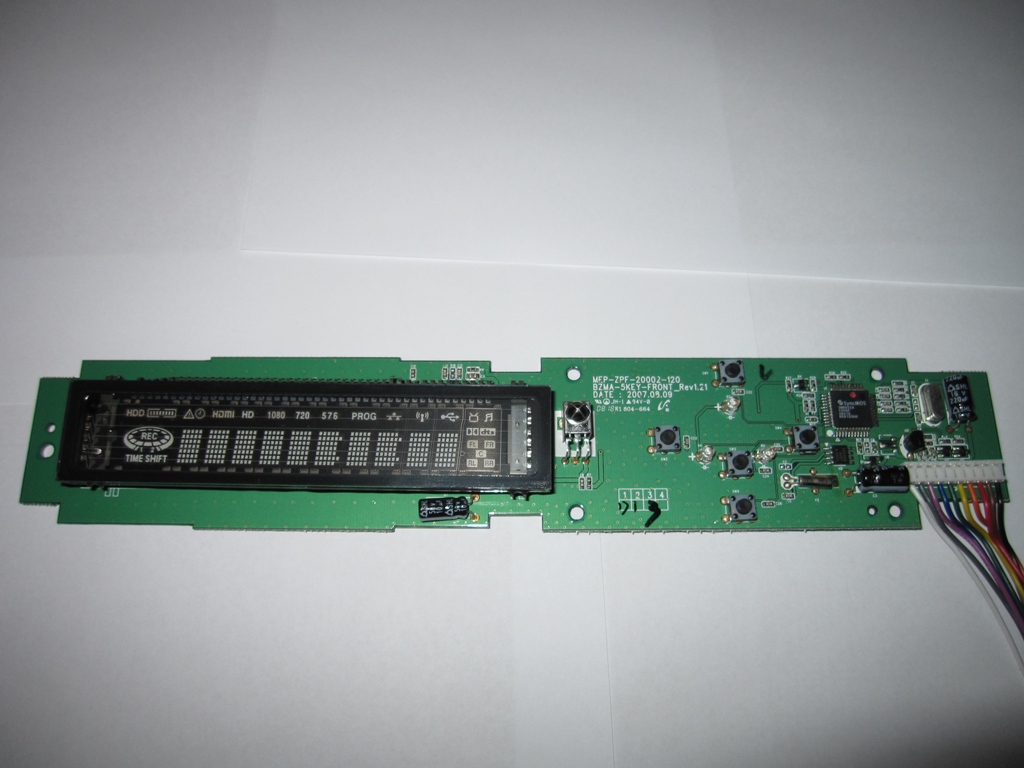
(PICTURE 1 ? The Front Panel PCB Of Your Wiz?)
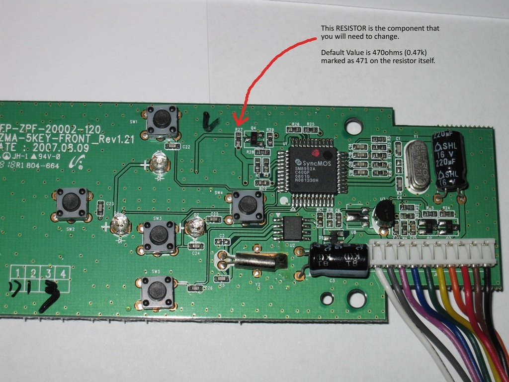
(PICTURE 2 ? The Front Panel PCB Zoomed In A Bit?)
When trying to source an SMD resistor of the value you decide on, make sure it is no bigger than 0602 or 0603 otherwise it will not fit properly between the 2 small solder pads. You basically want a clean straight replacement of this resistor, and whatever you do, DON'T get any idea's of cutting and moulding a standard 1/4 watt carbon resistor into this spot, it's not worth messing around. A packet of 10 of the correct SMD resistors should cost you no more than $2 at most.
------------------------------------------------------------------------------------------------------------------------------------------------------------
SECTION 3 ? REMOVAL OF THE FRONT PANEL
Now to REMOVE the Front Panel PCB from your Beyonwiz?
1. REMOVE POWER FROM THE BW, ensure that the power cable is unplugged, not just turned off. This sounds like the most obvious point doesn?t it, but surprisingly it isn?t!!!
2. Unscrew and remove the TWO (2) side case screws and FOUR (4) rear case screws from your unit and remove the lid by sliding it back and then lift it upwards.
3. Now unscrew FOUR (4) screws holding the front panel housing onto the metal frame of your unit. There are 2 screws on each side of the black housing.
4. There are actually 2 PCB's located in the front panel housing, one is the Memory card/USB board, the other is the Front Panel VFD board. These 2 boards each have a cable that connects onto the mainboard, you will need to unplug both of these cables from your mainboard now, to do this, follow the 2 cables from the front right corner of your unit onto where they connect on your mainboard, then push the clip in on each plug and gently pull up and off the board.
5. Push the 2 black plastic clips down on the top front edge of your unit to release the front housing from the metal chassis. The entire front housing should then turn downwards and come straight off with the 2 boards attached to it, and the 2 cables that you just disconnected as well.
6. Now unscrew and remove the FIVE (5) screws securing the VFD board to the front housing, and that's it, the VFD board should come straight off the plastic housing and should look like it does in Picture 1 in theory.
------------------------------------------------------------------------------------------------------------------------------------------------------------
SECTION 4 ? MODIFYING YOUR BLUE CIRCLE OF FIRE
This bit is pretty easy really... It is honest!
The basic steps are as follows.
* Unsolder R27 from the front panel VFD board. Be careful, it's very very small!
* Use solder braid to remove excess solder off the 2 solder pads on the board, but DO NOT heat these up to much or the pads will lift off the board.
* Resolder in a new 0602 or 0603 SMD resistor, preferably the recommended 4.7k value. They are not polarised so it does not matter which way it goes around.
Some tips to doing this...
Care very little about the existing resistor, just heat it up and flick it off, it's the fastest and easiest way, don't try anything fancy.
Once you clean the pads with the solder braid, they should be pretty much perfectly flat, so drop in the new resistor, and line it up using a small pair of tweezers, then "dot" solder onto one side of the resistor only to "hold" it into place, thus allowing you to remove the tweezers. Keep your hands steady when you do it. It does not matter how messy it looks at this point!
Once the resistor is temporarily held into place by the "dot" of solder, you can then properly solder the OTHER SIDE of the resistor cleanly, and then resolder properly/cleanly the temporarily soldered side thus fixing up your "dot" of solder.
Be very careful NOT to heat these tiny resistors up too much, or the metal ends will become unsolderable, and you will need to discard the resistor. That hopefully won't happen, but if it does it shouldn't be an issue considering these things usually come in a pack of 5 or 10.
That's it folks... Your all done.
------------------------------------------------------------------------------------------------------------------------------------------------------------
SECTION 5 ? RE-ASSEMBLING YOUR MACHINE
To REASSEMBLE your machine?
1. Place the modified front panel VFD board back into the black front housing, it locks into place if in the correct position.
2 Replace the FIVE (5) screws holding this board down.
3. Feed the 2 cables into your machine through the hole in the metal frame in the front right corner. Then ease the black front housing onto the metal frame tilting it from the bottom upwards until the 2 plastic clips lock into place again on the top, it might need a bit of a push as they are a bit stiff.
4. Replace the FOUR (4) screws, 2 on each side, to secure the black front housing onto the metal frame.
5. Reconnect the 2 cables back onto the mainboard.
6. Replace the LID of your machine and re-screw all SIX (6) screws into it.
------------------------------------------------------------------------------------------------------------------------------------------------------------
SECTION 6 ? BEFORE & AFTER PHOTOS
Well, I will say this, it is not easy portraying a dimmed Blue Circle in a photo, but I have tried as best I can...
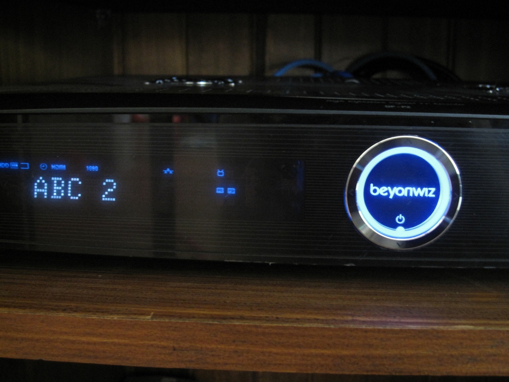
(PICTURE 3 ? A Photo of a DP-P2 Unmodified?)
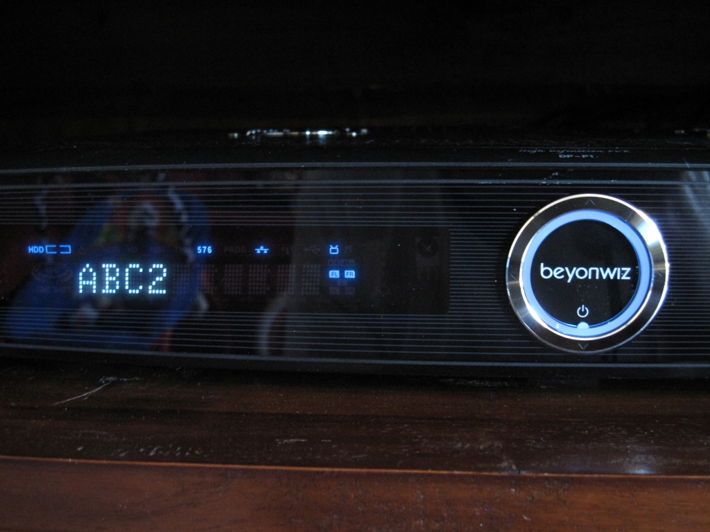
(PICTURE 4 ? A Photo of a DP-P1 Modified With A 4.7k Resistor?)
The photo's above are just of the front of the machines. taken during the day, they do actually show a brightness difference I think. It may not be obvious in these photo's but trust me, install a 4.7k resistor in here and it makes a MASSIVE brightness difference in the flesh so to speak.
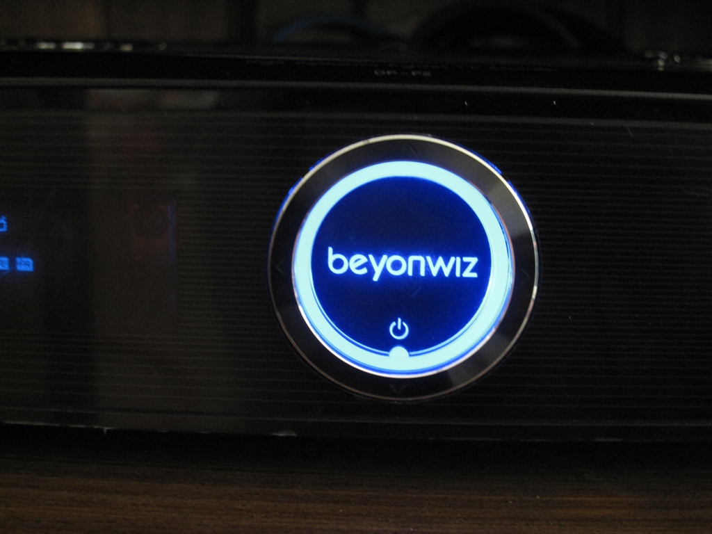
(PICTURE 5 ? A Photo of a DP-P2 (Close-up Of The Circle) Unmodified?)
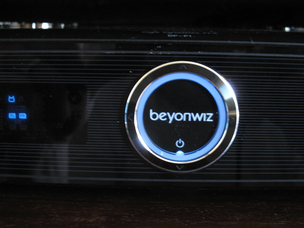
(PICTURE 6 ? A Photo of a DP-P1 (Close-up Of The Circle) Modified With A 4.7k Resistor?)
These should give you a better picture perhaps. Again these were taken in the daytime.
This next photo however was taken in a pitch black room, and no flash on the camera, so the only thing that shows up is the VFD display and the circle, here you can clearly see it is not mind blowingly bright anymore and is only a dull blue glow in reality.
Interestingly enough if you look at the VFD display in this next photo carefully, some of the blue icons on the display are actually brighter now than the circle is.
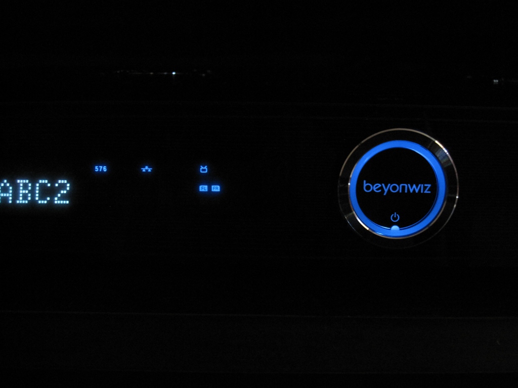
(PICTURE 7 ? A Photo of a DP-P1*In Total Darkness* Modified With A 4.7k Resistor?)
This I think demonstrates a reasonable example of how much dimmer it becomes, at least I hope so. Please remember also, this modification reduces the BLUE CIRCLE brightness down, NOT the VFD display brightness down.
I hope this assists many users with reducing the BCOF to a more suitable level.
Kind regards
Mark
------------------------------------------------------------------------------------------------------------------------------------------------------------
SECTION 7 ? REVISION HISTORY
Version History
1.0 - (27/11/2010)
Initial write up - 7 pictures included